Constructing Graphs
Flying Logic diagrams are technically known as graphs.
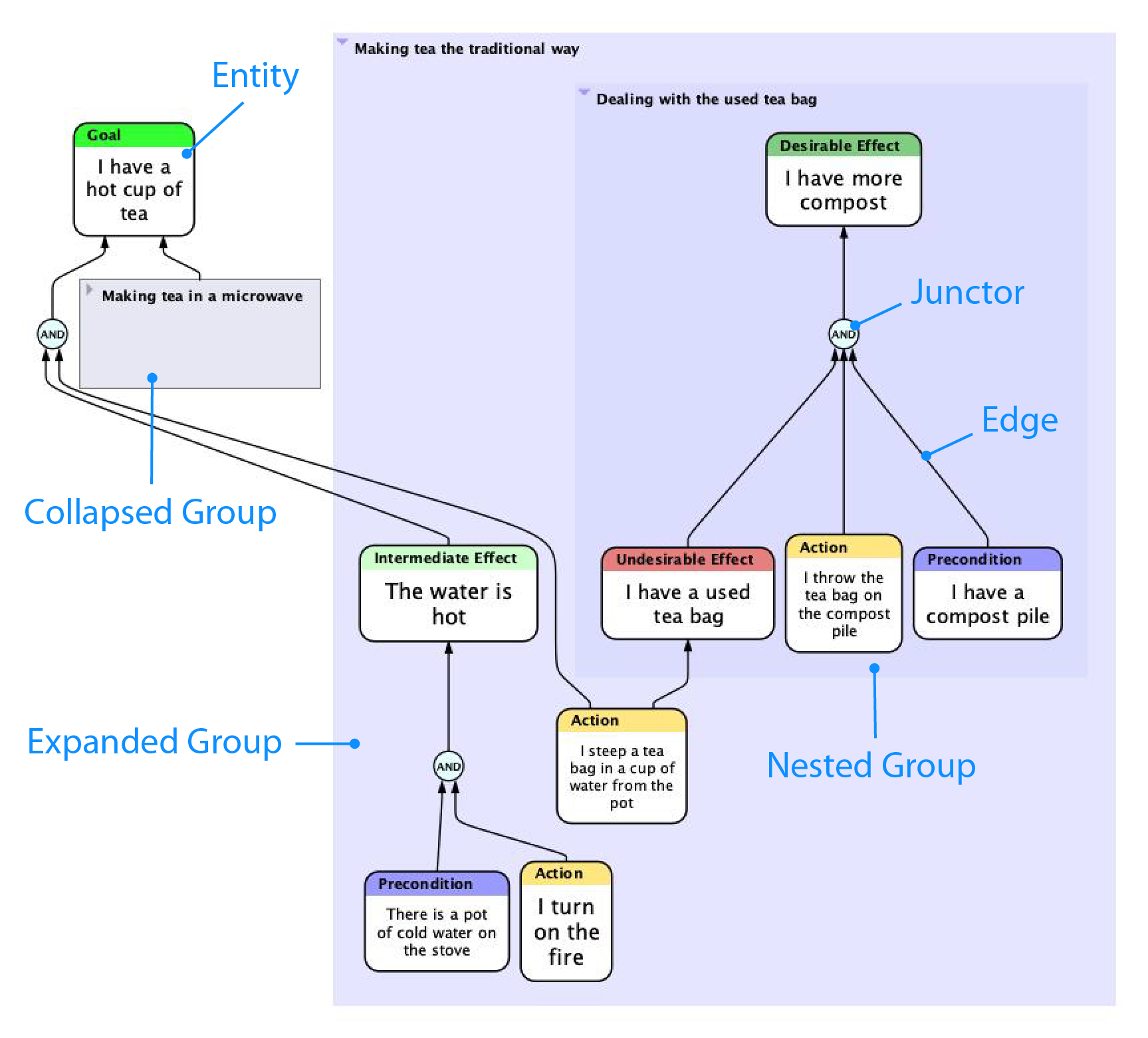
Flying Logic diagrams are technically known as graphs. A graph is a set of vertices (also called points or nodes) linked by a set of edges (also called lines or arrows.) Graphs can generally be used to represent many things, from street maps to social networks. In Flying Logic, graphs are often used to represent a network of causes and effects called entities and the causal relationships between them. The graph can also include junctors, which help you control the way the causal relationships combine, and groups, which help you organize your documents and manage larger documents.
Video: The Four Elements of Flying Logic
Working With Entities
Entities represent the causes and effects in your diagram. Each entity has a title, which is a short descriptive phrase, and can also include a much longer annotation. Entities also have a class, which is a word or two that describes what kind of entity it is, and that appears in a colored bar at the top of the entity. For a description of the classes built into Flying Logic, see Thinking with Flying Logic.
There are several different ways to create new entities within your document. Once you learn them, developing complex diagrams quickly will feel quite natural.
Add Entity as Successor
In the toolbar and Entity menu is the Add Entity as Successor switch:
.png)
The behavior of several commands and gestures used to add entities to the diagram depends on how this switch is set, and usually you will set it once depending on what sort of diagram you are building. You can also toggle the switch from the keyboard by pressing Command-Shift-E (Mac) or Ctrl-Shift-E (Windows or Linux).
The commands that use this switch either add a new entity pre-connected to an existing one...
...Or they first insert a junctor along the edge, then connect a new entity to it:

In the descriptions that follow, the  icon is read “predecessor or successor,” and appears whenever the setting of the Add Entity as Successor switch is observed.
Creating Entities With Menu Commands
- Select a class from the Domain Inspector, then select the Entity ➡ New Entity command or click the New Entity button in the toolbar. If an open group is also selected in the diagram, the new entity will be added to that group. If an entity or junctor is selected in the diagram, the new entity will be created as a (predecessor or successor depending on the switch) of the selected entity or junctor. If an edge is selected in the diagram, a new junctor will be inserted along the edge, and the new entity will be made a of the new junctor.
- Select a class from the Domain Inspector and also select an edge in the diagram, then select the EntityInsert Entity command or click the Insert Entity button in the toolbar. A new entity will be inserted along the selected edge.
- Right-click (Mac, Windows, Linux) or Control-click (Mac) on the gray diagram background or an open group, and select an entity class from the popup menu. A new, unconnected entity will be added to the clicked group or the top level of the document.
- Right-click (Mac, Windows, Linux) or Control-click (Mac) on an existing entity, edge, or junctor; then select an entity class from New Entity in the popup menu. If an edge was clicked, a junctor will be inserted along the edge, and the new entity will be added as a of the new junctor.
Creating Entities With Drag and Drop
- Drag a class from the Domain Inspector, and drop it either on an open group, or on the gray background of the Canvas. A new, unconnected entity will be added to the target group, or the top level of the document.
- Drag a class from the Domain Inspector, and drop it on an existing entity or junctor. The new entity will be created as a of the target entity or junctor.
- Drag a class from the Domain Inspector, and drop it directly on an existing edge. A new junctor will be inserted along the edge, and the new entity will be made a of the new junctor.
Creating Entities With Drop Zones
Flying Logic also has special DropZones that allow you to easily place new entities in precise relationships to existing diagram elements without needing to use the Add Entity as Successor switch. With a little practice, DropZones will become your favorite way to construct Flying Logic diagrams.
DropZones are near each edge, but not on the edge, and highlight when you move the cursor over them while dragging a class from the Domain Inspector.
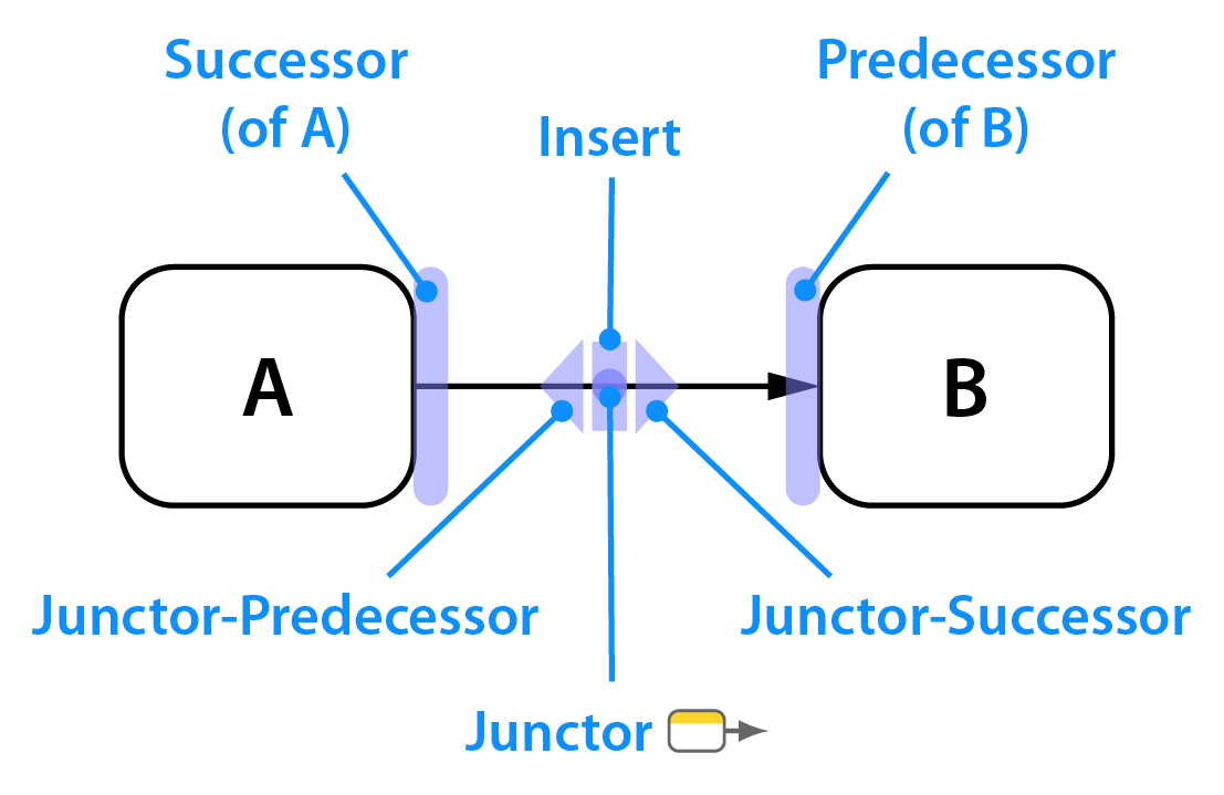
The position of the DropZones depends on the setting of the diagram orientation popup in the sidebar. In the examples below, the orientation is set to Bottom to Top. In this case, the Predecessor DropZone is underneath entities or junctors. If the orientation were set to Left to Right, as in the diagram above, then the predecessor DropZone would be to the left of entities or junctors.
- Drag a class from the Domain Inspector to the Predecessor DropZone of an existing entity or junctor:
- Drag a class from the Domain Inspector to the Successor DropZone of an existing entity or junctor:
- Drag a class from the Domain Inspector to the Junctor-Predecessor DropZone of an edge:
- Drag a class from the Domain Inspector to the Junctor-Successor DropZone of an edge:
- Drag a class from the Domain Inspector to the Insert DropZone of an edge:
Creating Entities Quickly
Flying Logic includes two ways to quickly create many entities: Quick Capture and the New Entities from List on Clipboard command.
Quick Capture
The Open Quick Capture button in the Toolbar allows you to create numerous entities quickly by simply typing their titles and pressing Enter. This is particularly useful when you are brainstorming with a group, and need to get a lot of ideas down quickly.
Quick Capture can be activated any time by pressing the E key, and can be exited by pressing Escape.
New Entities from List on Clipboard
If you copy lines of text to the clipboard, you can quickly turn them into entities by selecting the Entity ➡ New Entities from List on Clipboard command. This command creates the entities in the currently selected group, and assigns them the entity class currently selected in the Domain Inspector. It also intelligently detects line prefixes like bullets or other symbols and removes them.

Changing the Class of an Entity
To change the class of all selected entities, use one of the following options:
- Right-click (Mac, Windows, Linux) or Control-click (Mac) on the entity and select the desired class from the popup menu.
- Select a new class in the Class Popup of the Entity Tab of the Element Inspector.
- Option double-click (Mac) or Alt-double-click (Windows) on the desired class in the Domain Inspector.
Editing Entity Titles and Annotations
Double-click the entity to begin editing its title, or with an entity selected, press the Tab key. An editor appears over the entity that lets you type or modify the entity title. When you are done editing, press Enter/Return or click outside the editor to commit your changes. If the Text Inspector is visible, you can press Tab again to commit your changes and begin editing the entity’s annotation. Finally, you can press Escape to discard your changes.
You can directly edit an entity’s annotation by selecting the entity, then clicking in the Annotation Editor of the Text Inspector. When you are done editing, commit the change by clicking in the background of the Canvas. To remove an annotation, select and delete all the annotation text.
Annotation Numbers and Entity IDs
Flying Logic uses two different numbering systems that you can make visible in each document.
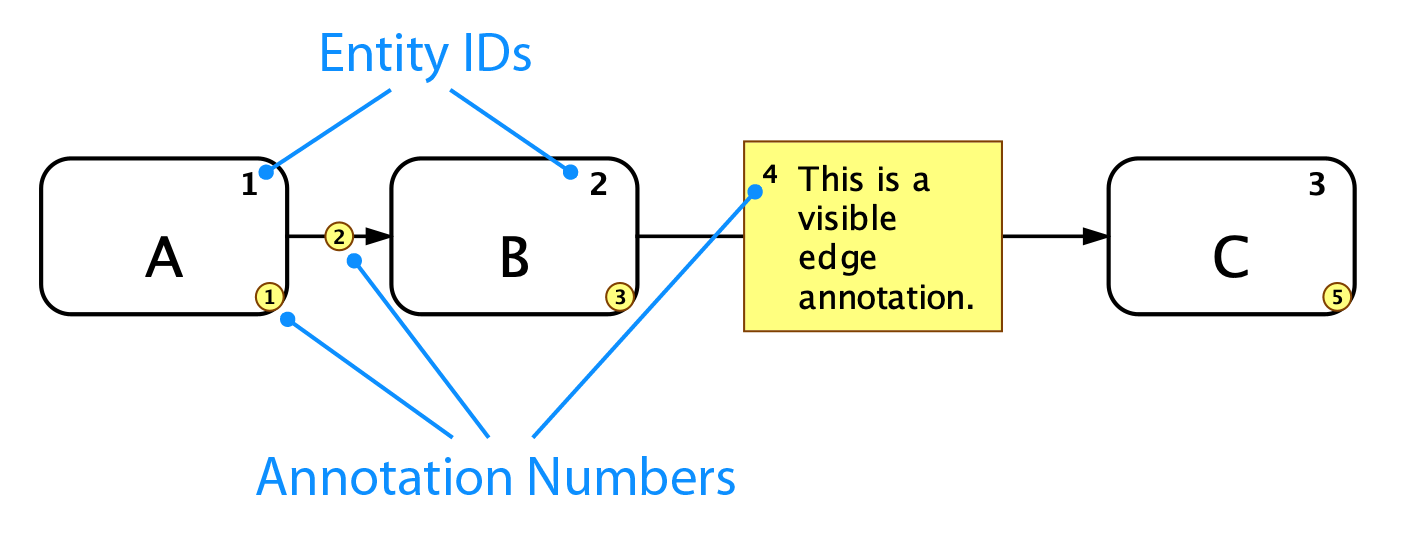
Annotation Numbers are revealed by clicking the Annotation Numbers icon in the Toolbar or by selecting View ➡ Annotation Numbers. Annotation numbers are primarily used for matching textual annotations (or their small yellow bullets) in the Canvas to the corresponding full text of the annotations exported using the File ➡ Export Annotations as PDF or File ➡ Export Annotations as Text commands. Unlike Entity IDs, annotation numbers are ephemeral and are renumbered every time the document is changed, which keeps the annotation numbers in the same order they appear along the flow of the document. This means that if you export notes from a Flying Logic document, then make changes to your document, you will need to re-export the notes for the exported numbers to match.
Entity IDs are revealed by clicking the Entity IDs icon in the Toolbar or by selecting View ➡ Entity IDs. Unlike Annotation Numbers, Entity IDs are durable and continue to exist throughout the life of the entity, unless the entities in the document are explicitly renumbered by using the Entity ➡ Renumber Entity IDs command.
Element Text Attributes
The View ➡ Element Text Attributes, dialog allows you to refine the way Flying Logic displays text throughout your document. The dialog contains three tabs for adjusting the attributes of entities, groups, and annotations. Each tab contains an area where you can preview the changes you make.
Entity Text Attributes
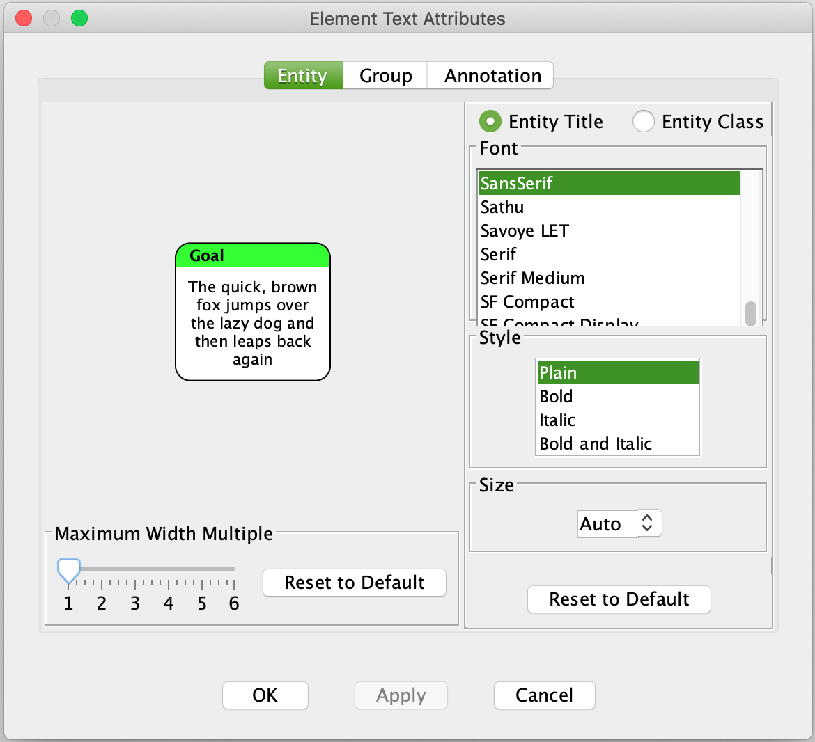
The two radio buttons in this tab let you choose between modifying the attributes of the entity title (the text in the white part of the entity) and the entity class (the text in the colored band at the top of the entity.)
When Font Size is set to “Auto”, Flying Logic selects a font size for entity titles based on the amount of text in the title:

By selecting a particular Font Size, you tell Flying Logic to use a fixed-size font for all entity titles:

Flying Logic normally chooses a fairly narrow width for containing entity titles, but this can cause long titles to be laid out taller than you might prefer. You can use the Maximum Width Multiple slider to ask Flying Logic to choose a width for long entity titles.

Clicking the Reset to Default button restores the default attributes for the tab.
Group Text Attributes
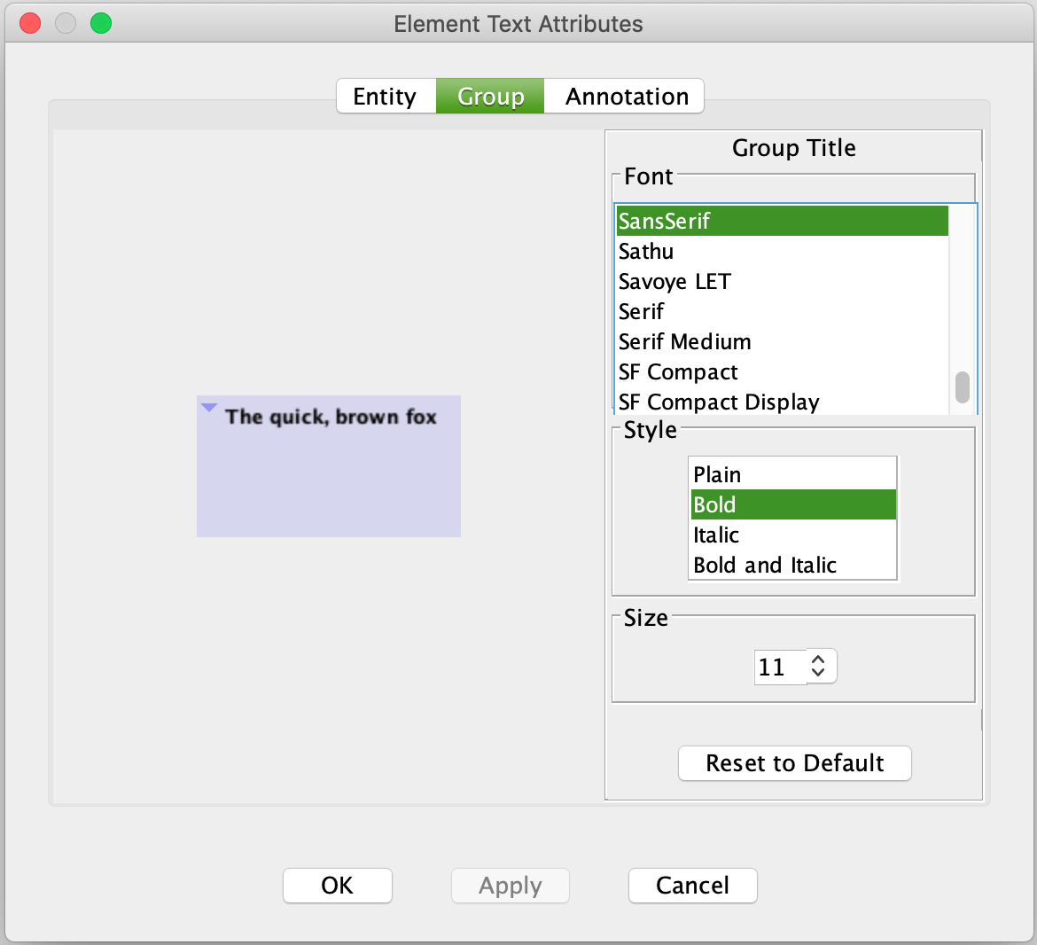
This tab lets you choose the attributes that are used to display group titles.
Annotation Text Attributes
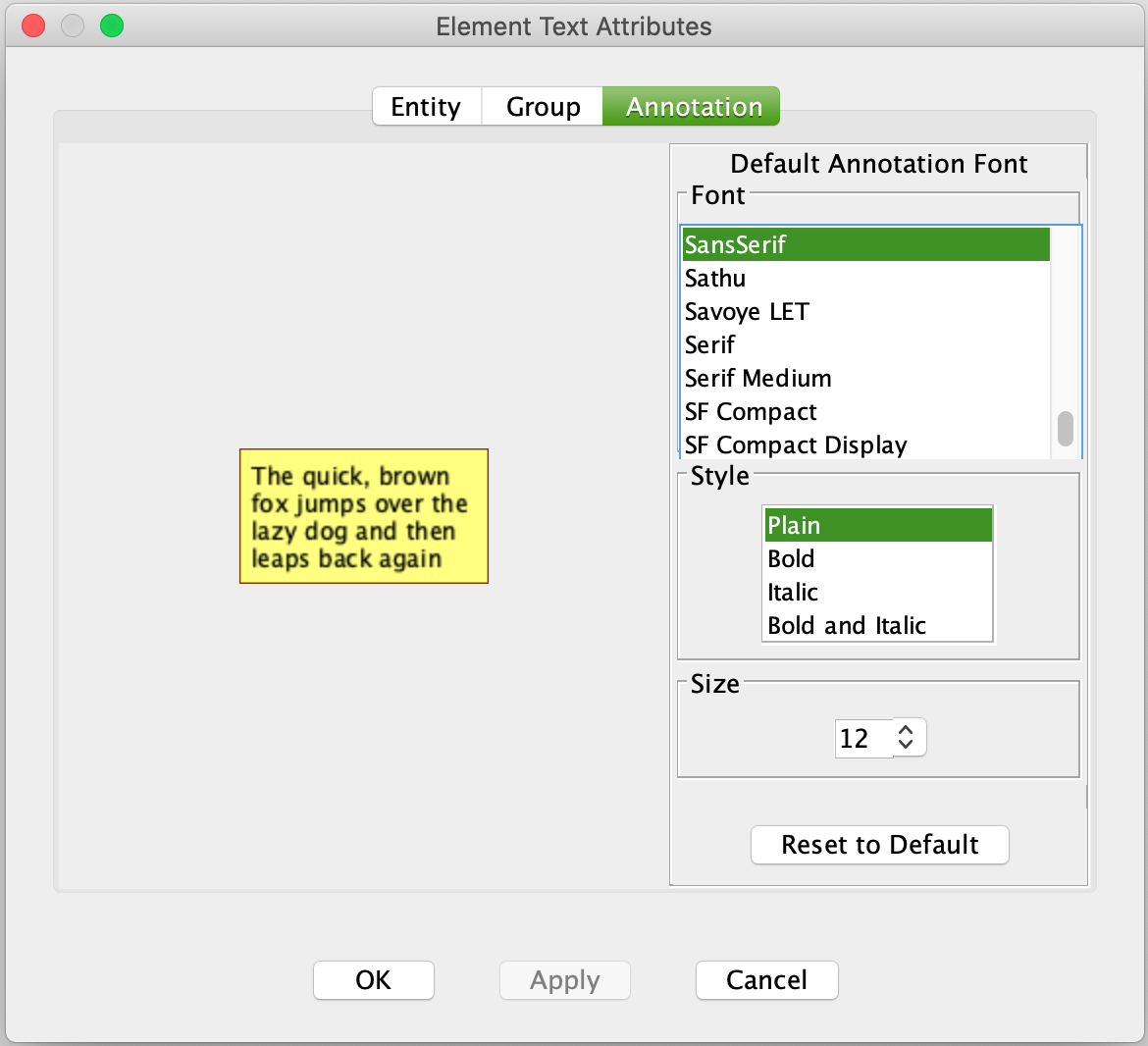
This tab lets you choose the default attributes that are used to display annotation text. As annotation text supports styles, this is the style that will be used in the absence of overriding styles.
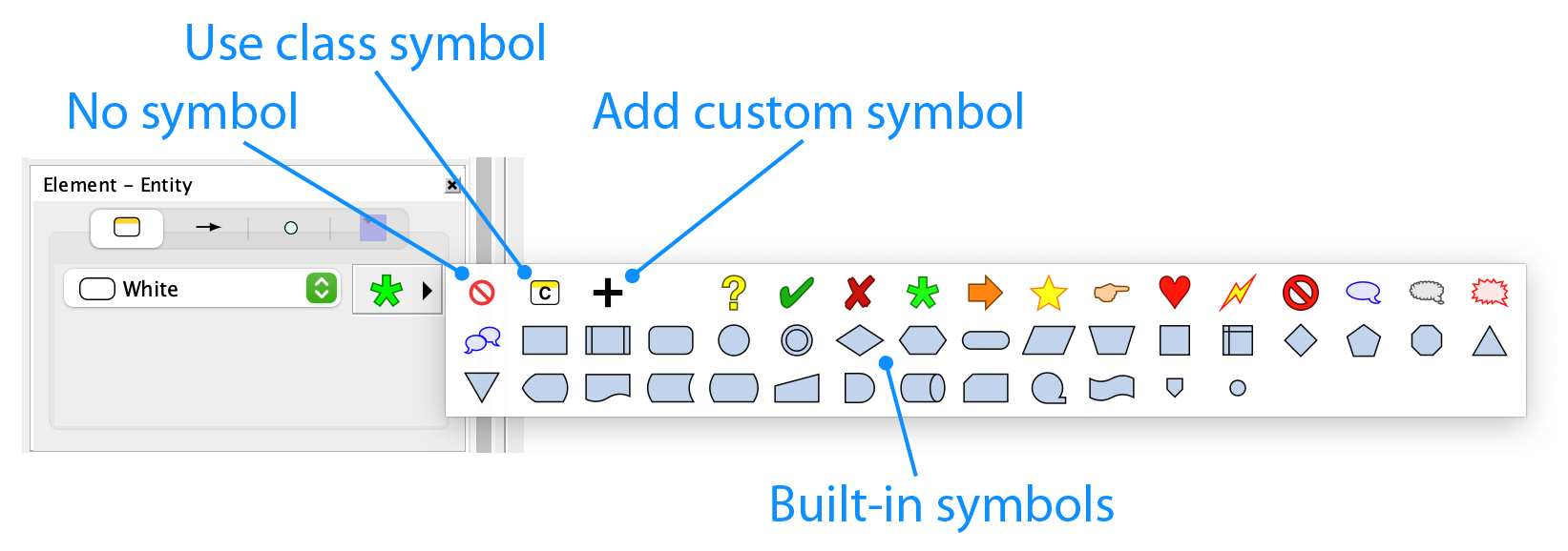
Assigning Symbols to Entities
To assign a symbol, select one or more entities, then select the desired symbol from the Icon Popup in the Entity tab of the Element Inspector. To remove a symbol, select the 🚫 icon in the upper-left corner of the popup.

Assigning Symbols to Classes
Symbols can also be automatically assigned to an entire entity class. For instructions on how to do this, see Creating A Custom Class. Whenever entities of such a class are created, the symbol will automatically apply to them, but can still be overridden on an entity-by-entity basis. To revert to the default symbol for a class, select the ![]() icon in the upper-left corner of the popup.
icon in the upper-left corner of the popup.
Adding Custom Symbols
In addition to the built-in symbols, you can add your own custom symbols from graphics files in SVG, PNG, GIF, or JPEG formats. Custom symbols are saved inside the Flying Logic document, so you can be sure that anyone to whom you send a Flying Logic document will be able to see your custom symbols without having a copy of the original image file.
- Click the + icon in the symbol popup menu.
- From the file chooser dialog that appears, select a SVG, PNG, GIF, or JPEG (JPG) document.
- A dialog appears that lets you select a part of your image to use as the symbol. Adjust the cropping rectangle and click the Accept button.
- Your custom symbol(s) appear at the end of the built-in symbols list in the symbol popup, and you can then assign them to entities (or classes) the same way you use the built-in symbols.
Small, simple images look best, and SVG (Scalable Vector Graphics) symbols look sharp at any zoom level or print resolution.
Managing Custom Symbols
Select Entity ➡ Manage Custom Symbols to display a dialog that lists all of the custom symbols embedded in your document, and also provides options for adding additional symbols, seeing which symbols are currently in use, and removing symbols from your document. Flying Logic will warn you if you attempt to remove a symbol that is currently in use.
Working With Edges
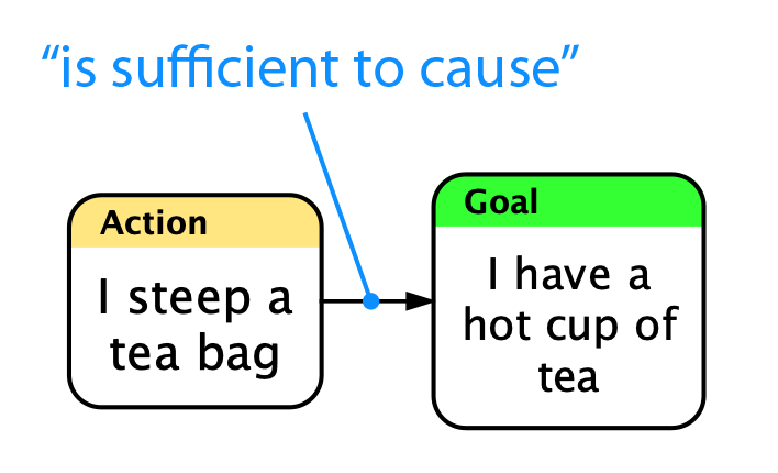
In Flying Logic, entities are connected to one another by causal relationships represented by edges. Each edge has a direction indicated by its arrowhead. In the way a Flying Logic document is set up by default, each edge represents the principle of sufficient cause. In other words, the existence of the state of affairs described by the entity at the tail of the arrow is sufficient to cause the state of affairs described by the entity at the head of the arrow. For a discussion of other possible ways to set up the meaning of edges, see Operators.
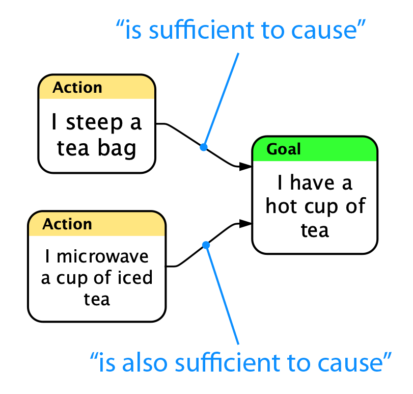
When there are two or more sufficient causes of an entity, then two or more edges point to it. The meaning here is that either OR both of the causes being true makes the effect true.
Creating Edges
To create an edge between entities, click and drag from the cause to the effect. While you drag, a distinctive gesture arrow appears to confirm that you are creating a connection.
Like other graph elements, edges may have annotations attached to them.
To create edges from a selected set of entities to an entity far away in the graph, you can ALT-Left-Click (Option-Left-Click on Mac) on that other entity.
Parallel Edges
Flying Logic disallows parallel edges, in other words: more than one edge from a particular cause to a particular effect.
Back Edges
Flying Logic supports back edges (also called cyclic edges or loops), which are edges that (directly or indirectly) make an effect to be its own cause. When a connection is made that requires a loop, a back edge is created automatically. Back edges are thicker than regular edges.
Unlike regular edges, back edges do not participate in calculations— confidence values do not flow through them and their weights are ignored. They can be annotated like any other edge. Supporting back edges allows relationships such as virtuous and vicious circles to be diagrammed, while keeping the basic model a directed acyclic graph.
Moving Edges
As you build your diagram, you will often discover that the head or tail of an edge needs to be moved to a different entity (or junctor). This is easily accomplished by clicking and dragging near the end of the edge you want to move and dropping over the entity (or junctor) where you want to reconnect it. Before you click, you will see a highlight appear near the end of the edge that you will be moving. While you drag, a distinctive gesture arrow with a circular head appears to confirm that you are moving an edge. You can also drop over another edge, which will cause a new junctor to be inserted on that edge.
Reversing Edges
Edges normally point from causes to effects. If you discover that your document has an edge pointing “backwards” from an effect to a cause, this can easily be fixed by reversing the edge. All currently selected edges can be reversed with the Edit ➡ Reverse Selected Edges command. Note that “reversal” here refers to swapping the elements at the head and tail of an edge, and not to the direction the edge points, which is usually determined by the Orientation popup of the Layout Inspector.
Swapping Elements
You can also swap any two elements of the same kind with the Edit ➡ Swap Selected Elements command. This command simply causes the two selected elements of the same kind (entities, junctors, edges, or groups) to switch places, including any attributes such as annotations, edge weights, or group color.
Swapping Forward and Back Edges
When you are creating diagrams that involve back edges, it is sometimes nice to be able to choose which edge in a loop should flow against the direction of the rest of the document. You can accomplish this by selecting a back edge and a forward edge, then choosing the Edit ➡ Swap Selected Forward and Back Edges command.
Working With Junctors
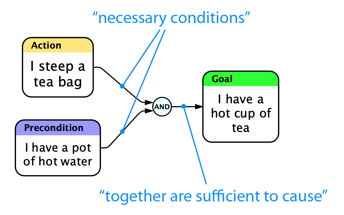
Frequently, effects are brought about only by the several causes in combination. Junctors are small circles that contain the name of an operator such as AND or OR. Since more than one edge entering an entity is, by default, already considered to be an OR operation, junctors are often used to represent AND, which is the idea of necessary condition: that several causes are each necessary but none of them alone is sufficient.
Creating Junctors
As we’ve seen, creating edges is as simple as dragging from cause to effect. Creating junctors is equally simple: drag from the cause to the edge where the new junctor should appear. You can also right-click (Mac, Windows, Linux) or Control-click (Mac) an edge and select an operator type from the Insert Junctor section of the popup menu.
Any combination of dragging from entities, edges, or junctors to other entities, edges, or junctors will result in a new connection being made, as long as it would not result in a parallel edge. If the start or end (or both) of the drag is an edge, a new junctor will be inserted there and the new edge connected to it.
Preconditions are causes that are outside of your control, while Actions are causes inside your control. For more information about the entity classes used in these examples, see Thinking with Flying Logic.
Entities, Junctors, and Edges
There is a difference between how entities and junctors are related to the edges that connect them. The existence of entities is independent of their edges, while the existence of junctors is dependent on their edges. That is, an entity can exist whether or not it is connected to any other part of the diagram: it may have edges entering it or leaving it, or both, or it may be unconnected to anything. On the other hand, junctors must always have at least one edge coming in and one edge going out— if the last edge either entering or leaving a junctor is removed, the junctor itself will also be automatically removed.
Working With Groups
Groups help you organize your diagram and manage the complexity of larger diagrams. Groups appear as shaded rectangles that enclose entities, junctors, and other groups. Like entities, groups may have both titles and annotations, which are edited in exactly the same ways as for entities.
Creating Groups
You can create groups using the Entity ➡ New Group command, or by clicking the New Group button on the toolbar.
- If there is no selection, the new group will be created by itself outside all other groups.
- If there is a selection, the new group will enclose every element in the selection.
Setting the Group Title
To change the title of a group: double-click it, edit the text in the field that appears, then click outside the field to finish the change.
Arranging Grouped Elements
Individual elements and selected sets of elements can be moved into, out of, and between groups by dragging. First, select the elements you wish to move to a different group. Then drag any of the selected elements into the new group. While you drag, a distinctive gesture arrow with a square head appears to confirm you are rearranging objects within groups. Groups can also be nested within other groups using this technique, and you can also move elements out of any group by dragging to the gray canvas background.
Collapsing and Expanding Groups
Groups can be collapsed (or expanded) to hide (or reveal) their enclosed elements.
- To collapse (or expand) a group, click the small triangle that appears in its upper-left corner. Option-click (Mac) or Alt-click (Windows) to collapse (or expand) all nested groups within the group as well.
- The Group Tab of the Element Inspector contains four buttons that explicitly perform the above operations: Collapse, Expand, Deep Collapse, and Deep Expand
When a group is collapsed, any edges connected to elements both inside and outside the group appear to be attached to the group. Expanding the group will show the actual point of attachment.
Group Colors
The Group tab of the Element Inspector contains a popup menu that lets you select the color of the currently selected group(s). This can be useful as a way of visually identifying or categorizing groups.
Assigning Symbols to Groups
Like entities, groups can also be marked with a symbol. Select one or more groups then select the desired symbol from the Icon Popup in the Group tab of the Element Inspector. To remove a symbol, select the 🚫 icon in the upper-left corner of the popup.
Hoisting
Hoisting views the contents of a single group as the entire contents of the canvas, as if it had been raised (hoisted) up to the top level. Hoisting makes it much more convenient to work on parts of documents that are nested within groups, even down several levels.
In the following illustration, we wish to work purely inside Group 2. To do so, select the group, then the Group ➡ Hoist Selected Group command. After hoisting, the canvas only contains elements from within Group 2, as well as edges that enter or leave it along with icons representing the entities at the other end of those edges. The icons cannot be edited, and in fact they are part of the entering or leaving edge itself.
Let’s say that after editing Group 2 for awhile, we need to see its contextual parent group, Group 1, but we’re not yet ready to unhoist all the way back to the top. Selecting the Group ➡ Unhoist One Level command accomplishes this.
To return to the top level at this point, we could either select the Group ➡ Unhoist One Level command again, or use the Group ➡ Unhoist to Top command, which would return us to the top level no matter which group was previously hoisted.
When a group is hoisted, the Path Bar appears along the top of the canvas, indicating how many levels deep you are viewing, and the names of the groups you must traverse to get back to the top level:
Clicking any segment of the Path Bar to the left of the last one unhoists to that level in a single step.
Flying Logic does not save the current hoisting level in the document file. Therefore, each time you open a document Flying Logic will show the entire document, even if it was saved while a group was hoisted.
Printing or exporting a Flying Logic document in image formats such as JPG, PNG, or PDF takes into account the groups you have collapsed and the currently hoisted group, if any, along with your other layout settings. In other words, what you see before you export or print is what you will get in the resulting output. Exporting in non-image formats like Microsoft Project or OPML always exports the entire document.
Selections
Flying Logic lets you select several diagram elements upon which to perform operations.
- You can select an individual element by clicking it.
- You can use the arrow keys to move the selection from element to element.
- Additional elements can be selected (or deselected) by Shift-clicking.
- Holding down the Shift key and pressing the arrow keys “expands” the selection in the direction you specify.
- Marquee selection can be used to select several elements with one gesture. Option-click (Mac) or Control-click (Windows or Linux) in the gray background area of the graph and drag the selection rectangle over the elements you wish to select. Additionally, starting marquee selection with Shift-Option-click (Mac) or Shift-Control-click (Windows or Linux) will toggle the selected/not-selected state of the objects you drag over. If you begin your marquee selection inside a group, only elements within that group are eligible for selection.
Deleting Selections
All selected elements can be deleted by pressing the Delete key, or by clicking the Delete button in the toolbar. Like all Flying Logic actions, deletion is undoable.
Deleting a group does not automatically delete any enclosed elements (unless they are also explicitly selected.) Instead, the enclosed elements are “promoted” to the next higher group, if any. Deleting a selected group along with all its enclosed elements (including other groups) can be accomplished by pressing Command-Delete (Mac) or Control-Delete (Windows).
Copy and Paste
Selected elements can be cut, copied, and pasted within and between Flying Logic documents. When you make a selection and select the Edit ➡ Copy or Edit ➡ Cut command, or click the corresponding toolbar icons, the selection becomes shaded orange (for copy) or red (for cut). You can cancel a pending Copy or Cut any time by pressing Escape. Once you have a shaded selection, select the group (or no group at all) in any document you wish to transfer the elements to and select Edit ➡ Paste or click the Paste toolbar icon.
Layout
Your job is to make a diagram that accurately models your problem. Other than a few simple choices, such as whether your diagram flows from bottom-to-top or left-to-right, working out how the various graph elements are laid out is purely Flying Logic’s job. Sometimes Flying Logic may surprise you by making layout choices different from those you might have made, but it will often make better choices than most people, especially when the graph becomes complex. Each time you change the structure of the graph, Flying Logic uses animated transitions to show you what has changed. You can control the speed of the animation. See Preferences.
Orientation
Flying Logic documents “flow” in a direction specified by the Orientation Popup of the Layout Inspector. Which you choose for your diagram depends on the usual flow for the kind of diagram you are creating, compactness, or simply which one looks best to you.
If you find yourself using one orientation for new documents, you can select the default orientation used by new documents. See Preferences.
Side-To-Side Orientations
Use the side-to-side orientations for diagrams that naturally represent dependency flows.
Layout Orientation
Radial Orientations
Use the radial orientations for diagrams that naturally represent trees or parts explosions.
.png)
Inner to Outer Radial Layout
.png)
Outer to Inner Radial Layout
Radial orientations work best when the diagram is a true tree— that is, where each “parent” entity may have multiple “children”, but where each “child” may only have a single “parent”. Whether you choose Inner To Outer or Outer to Inner depends on whether you want arrows pointing outward or inward with respect to the root of your diagram.
Changing Orientation does not change which entities are at the head and tail of edges: if you need to reverse edges in one step, simply use the Edit ➡ Reverse Selected Edges command.
Bias
The layout bias of a document tells Flying Logic whether to prefer pushing elements closer to the start of the flow, or closer to the end of the flow. Which you choose can strongly impact the style of your diagram.
Compactness
The compactness of a document controls the tightness of the the space between entities.
Incremental Layout
Each time you change your document, Flying Logic lays it out again in order to keep the diagram compact and minimize edge crossings. Normally, Flying Logic performs a full, “from scratch” layout of your diagram, which results in a highly efficient and clear result. However, this full layout does not take into account the starting position of the graph elements, and therefore can sometimes cause a large amount of visual change, even causing the entire diagram to appear to flip over. These large shifts can make it hard to follow even small changes, and the larger the diagram, the worse the problem.
By turning on Incremental Layout using either the toolbar icon or the View ➡ Incremental Layout command, you tell Flying Logic that you want to have each layout depend on the results of the previous layout. In the following illustration with Incremental Layout on, the relative positions of all the entities stay mostly the same.
The advantage of Incremental Layout is that you can make a large number of changes to your document with less visual disturbance. The downside is that with Incremental Layout on, the layout will get progressively less efficient, particularly in its use of space. You may also see edges flowing against the general flow of the layout, or unnecessary line-crossings being introduced. When it is convenient, you can turn off Incremental Layout to cause Flying Logic to do a full layout.
Flying Logic does not save the position of a document’s elements (the result of the layout) in the document file. Therefore, each time you open a document, Flying Logic will perform a new, full layout, even if it was saved while Incremental Layout was on.
Managing Large Documents
Keep the following guidelines in mind when working with large Flying Logic documents.
Managing Memory
Flying Logic provides a Memory Gauge to the right of the Title Editor in each document window that shows the amounts of memory in use (dark blue) currently allocated to Flying Logic (medium blue) relative to the maximum the application will ever request (light blue).
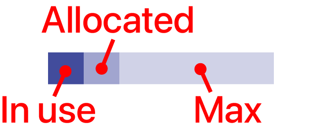
As you work, the dark blue bar will rise and fall again as Flying Logic reclaims unused memory. As your document becomes larger, the medium blue bar will also grow, but will never get smaller until you restart Flying Logic. Memory only becomes a serious consideration when the dark blue bar starts occupying the entire width of the Memory Gauge most of the time. If this happens, try closing unnecessary documents or restarting Flying Logic.
Managing Graphic Complexity
You may notice that Flying Logic redraws, animates, or responds to user actions more slowly when a diagram becomes large and complex. Here are some ways to mitigate this:
- Use groups to enclose parts of your diagram you’re not working on, and then collapse those groups. Collapsed groups are fast to draw and can contain any number of diagram elements.
- Use the Zoom control to display less of the diagram at one time.
- Use the Navigation Inspector to move around a large document.
- Use Hoist to focus on particular groups you're working within.
- Experiment with the Display Animation Preferences settings. See Preferences.
- Consider breaking your diagram into two or more sub-diagrams in separate documents.